The tradeoff is quite complex, but in principle the sensitivity of the PA output is inversely proportional to the load-impedance required to obtain the output power.
- On PA_BOOST, regulated PA, we're getting 17 dBm with only about 1.65 V of DC bias, in order to maintain it from 1.8 to 3.7 V. This calls for a fairly low load impedance (P=V^2/Z).
- On RFO, we are targetting much lower power, 14 dBm, with direct attach to VBAT, nominally 3.3 V. Therefore, the load impedance is much lower.
You can grasp that a mismatch at the antenna will have less impact on RFO than it does on PA_BOOST (less impedance transformation). The OCP block is here to limit the current drain, protecting your power supply or battery in case of severe mismatch conditions.
The RSSI (Receive Signal Strength Indication) value corresponds to the estimation of the received input power signal at the antenna seen by the gateway. There is no block at the antenna to perform this estimation, but a baseband RSSI "sx1301_rssi " is estimated inside the SX1301 chip. Then the RSSI (at the antenna) is calculated by subtracting the gain of the Rx chain "Rx_gain" to the baseband_rssi:
sx1301_rssi = Input_level_antenna (=RSSI) + Rx_gain
This implies that RSSI = sx1301_rssi €" Rx_Gain.
The RSSI value is read from the SX1301's packet buffer and is then summed with the rssi_offset:RSSI = sx1301_rssi + rssi_offset => so rssi_offset = -Rx_gain
The accuracy of the RSSI value depends of two factors:
- The estimation error of the signal envelope power done by the SX1301
- The estimation error of the Rx gain
The Rx gain includes analog gain (from antenna to ADC block) as well as digital gain. The analog gain, by nature, can change from one gateway to another one. "rssi_offset" can then be used to calibrate/compensate any Rx gain variation.
The RSSI parameter can be used for following features:
- Rx AGC (managed by the gateway itself)
- ADR (Adaptive Data Rate)
- Downlink message (to choose the best path/GW when corresponding uplink message has been received by several gateways)
Path loss in the sub-GHz spectrum is now well studied and documented, thanks to analysis done by the cellular industry over the last few decades.
Both line-of-sight and urban-type models are available, such as the Friis formula for line-of-sight, and COTS-231 for urban environments.
Path loss estimations are compared to the link budget of the LoRa technology, which can be estimated by summing the effective radiated power of the transmitted (typically 14 dBm in Europe and Asia), and the sensitivity of the received (down to -137 dBm).
Depending on the network server used, the antenna gain offset calculation is done in the server or in the gateway. In recent versions of the packet forwarder, there is an entry in the"global_conf.json" file that looks like this: "antenna_gain": 0, /* antenna gain, in dBi */
This "antenna_gain" can be used to compensate the gateway Tx Ouput Power "rf_power" by the gateway itself, not by the network server. Indeed, the "rf_power" field for each entry of the Tx LUT, defined in the "global_conf.json" too, corresponds usually to the conducted Tx Output Power, not the radiated one.
For instance, the "rf_power" along with its gain fields ("pa_gain","mix_gain" and"dig_gain") can come from a generic/conducted (i.e. without any antenna) calibration performed at production time. So, afterwards, you can define the "antenna_gain" in the"global_conf.json" configuration file to take into account any gain of the antenna mounted on the gateway in the field.
In the packet_forwarder program of the gateway, the "antenna_gain" field is subtracted from the "rf_power" field for all Tx LUT entries as follow: final_rf_power = rf_power - antenna_gain. "antenna_gain" must be a signed 8-bit integer, from -128 to +127.
The Frame counter shall never reset, as it would indicate a potential security issue to the network server. The Security White Papers published by the LoRa Alliance address this point.
The sensitivity of the LoRa Technology does not depend on the environment in which it is installed. However the propagation will be much worse underground, due to penetration loss. As a first guess, you could estimate 20 to 30 dB of penetration loss for underground systems.
The maximum bitrate in LoRa is with SF7/bandwdith 500 kHZ and we will be at around 21 kbit/s while HD1080p video bitrate is around 5 Mbit/s in a wire without any handling of packet loss. The LoRaWAN protocol is unfortunately not made for this kind of application.
Let's get the maths going:
One picture with 640 x 480 pixels and 8 bit color code (which is not great) would give you three bytes per pixel (R,G,B color code). This would lead to 921.6 kB of raw data to transmit without any overhead (preamble, header, frame counter,etc). This is a huge amount of data, even at 50 kbit/s, and would take several minutes to send between two devices.
The usually accepted simplification consists of taking into account the Signal to Noise Ratio (SNR) and combining it with RSSI.
- if SNR > 0: packet power = RSSI
- if SNR < 0: packet power = RSSI + SNR
RSSI and SNR expressed in dBm and dB respectively.
No, it may marginally pick up, but with no guarantee of successful detection. The bandwidth and spreading factor must be set to the proper value for the Channel Activity Detection (CAD) to work.
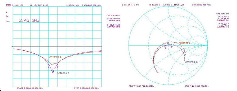
The following data shows the impedance of the two antennas on the SX1280 development kit, with the impedance matching. Here we see in excess of 16 dB of return loss which is good for a portable antenna.
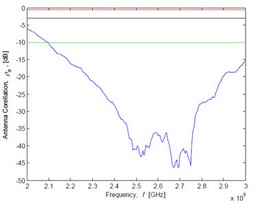
The figure below shows a representation of the antenna system diversity performance, based upon the measured antenna S Parameters. (Based upon the method of Blanch et al). Here the red threshold indicates poor diversity performance, black acceptable diversity performance and green good, i.e. useful, antenna diversity performance.
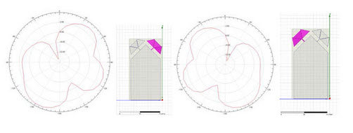
The final plots show the simulated radiation patterns of the two diversity antennas. The pattern corresponding to the highlighted antenna (with the pattern in the same orientation as the board image).
Whilst the ranging performance accuracy is not dependent upon the received signal power (for an example of this and to see how to set up your first ranging measurements, see our application note for more details). It is important to note that the group delay of the transmitter will change depending upon the programmed transmit power.For this reason it is necessary to include a calibration setting for every programmed output power you intend to use in your final application. Our Introduction to Ranging application note gives more information on how to perform the calibration for your design.
A common regulatory test requires setting the radio to a continuous modulated signal and measure the radio spectrum energy of the transceiver when transmitting packets. Typically the occupied spectrum will refer to the band width between the lowest frequency 3dB below the peak and the highest frequency 3dB below the peak of the signal of interest. To this aim, it is often required for the radio to transmit pseudo-random payloads. The transceiver datasheets provide a description of radio functions that can be used for this purpose. See chapter 17, Test Commands, of the LR1110 User Manual for one example.
There are changes required at the host interface and specifications for transmitting data in a LoRa system that require changes to the host system software, but with fully integrated modems available in the eco-system, and their well-defined host controller interface, it is actually quite seamless.
This is possible, but there would be a need to convert an existing 802.15.4 or other mesh protocol to use the modulation format.
Because of some of LoRa's features such as longer transmission time which increases link budget and the availability of a relay specification, LoRaWAN is usually the best choice.
The SX1301 device is the baseband signal processor for LoRa gateways. It takes 32 MHz, 1-bit I/Q digital baseband samples as an input. It is generally paired with two SX1257 front end digitizers, though it can be used with other forms of digital RF. This is often done with the 8 x SX1301 gateway architecture Senet uses in its network deployment.
With SX1261/62 and LR1110 it is possible to transmit and receive the LoRa modulation at any frequency between 150 MHz and 1 GHz, such as 169 MHz, 433 MHz, etc. even in the licensed spectrum.
Additionally, LR1120/21 offers also the possibility to operate in the 2.4GHz ISM Band, as well as in the licensed bands used by SATCOM.
The Semtech gateway reference designs have been engineered to operate in the 490MHz, 868MHz , 915MHz and 2.4GHz bands, although they could be easily adapted for other frequencies.
SX1272 has three programmable LoRa bandwidth settings: 500 kHz, 250 kHz and 125 kHz. It covers bands from 850-1 GHz.
SX1276 has bandwidths from 500 kHz to 7.8 kHz, and covers 150 MHz bands, 433 MHz, and 850-1 GHZ.
A device's uplink can be received by two or more networks simultaneously, Typically the gateways are configured to ensure overlapping over multiple channels, at least the joining channels.
Passive roaming is transparent for the device, it has no specific action to undertake. Passive roaming is defined for two flavours:
- Stateless, where the visited network forwards all uplinks and downlinks, of a given netID.
- Statefull, where the visited network may perform some filtering on the traffic from the devices.